How to make the UV-C irradiator head
by Dave Keenan, 1-May-2005
http://d.keenan.com
This UV-C irradiator head is one component of my low-energy chemical-free swimming-pond filtration system. This system and the instructions for building it represent a year of self-funded (or should I say wife-funded) research and development.
I understand that while many people will feel confident to construct the undergravel filter and maybe even the pump, some may be less confident to construct this UV head or the power supply and control box. There are two option in this case: (a) pay someone else to construct it for you, or (b) do without it, while understanding that there may be additional health risk. If you don’t use the UV head you will simply replace it with a plain 65 mm PVC elbow and outlet pipe.
Note that it was necessary to design and build this UV unit myself because I couldn’t find any commercial unit which combined extra-low-voltage (ELV) with submersibility and axial flow. The same goes for the pump. You will find commercial pumps and UV units with two of these properties but never all three. Submersibility and axial flow are necessary for energy efficiency while ELV is essential for safety and legality. You can use 230 Vac submersibles in fish ponds but not in swimming pools.
Parts list
From http://www.rockaroundtheblock.com.au or other fish-pond or water-feature supplier:
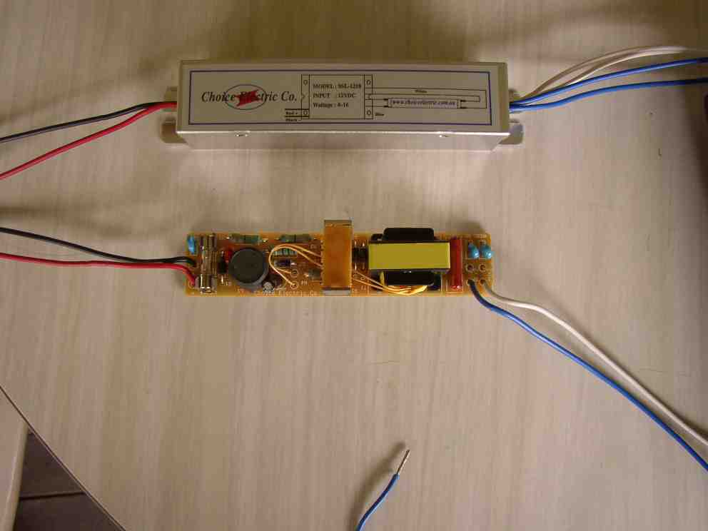
From http://www.choiceelectric.com.au
From boating supplies or electronics supplies
Hardware
Electrical supplier:
Electronics supplier, e.g. Jaycar
Tools
Method
Cut a piece of 40 mm PVC DWV pipe 200 mm long for the inverter housing.
Cut another piece of 40 mm PVC pipe 42 mm long. Mark 2 lines on it lengthways, 16 mm apart and cut out and discard the material between them. This sleeve will be compressed and fitted inside the 200 mm piece of pipe to take the weight of the inverter, so it is not pressing on the lamp.
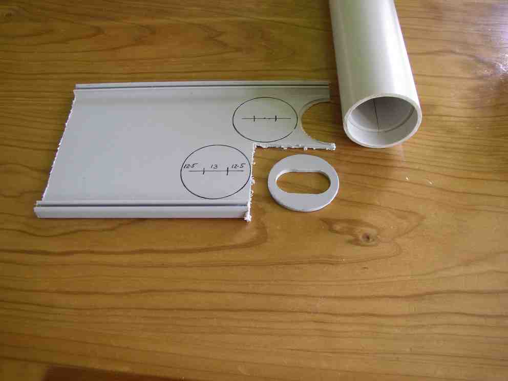
From a piece of flat PVC 2.5 to 3 mm thick, or from a second pipe end-cap, use the 43 mm holesaw to cut a disk that will fit inside the 40 mm pipe. This disk is to take the weight of the lamp so it is not pressing on the edge of the outer quartz sleeve, and to reduce air movement that might tend to cool the UV lamp below its optimum operating temperature and overheat the inverter. A 44 mm (1 ¾") holesaw will cut it oversized, but it can then be trimmed down roughly to size with shears or a knife, then filed or sanded. Draw inside a pipe off-cut to mark it. This disk will be about 38 mm in diameter. In this disc, use a 16 mm (5/8") holesaw to cut two symmetrically placed holes whose centres are 13 mm apart (so about 12.5 mm from the edges). Use a knife and file to cut off the cusps remaining between the two holes, to make an oval hole. The quartz tubes of the lamp should pass easily through this hole, and the first millimetre of the lamp’s metal collar should just pass into the hole.
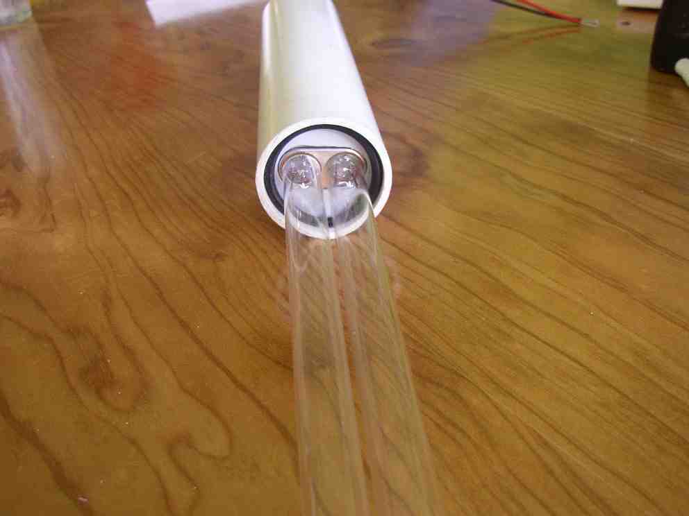
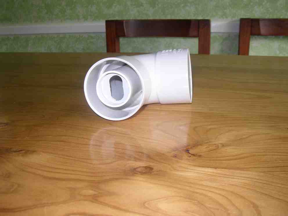
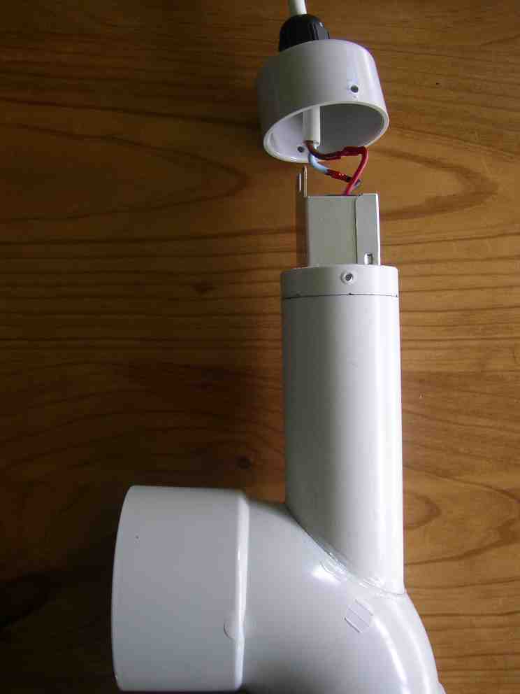
Push the 42 mm sleeve into the 200 mm tube until it is completely inside. Then put the disk against it and push it further until the disk is 10 mm inside the pipe. Remove the disk by pushing it out with a rod from the other end. Liberally run PVC cement around the end of the sleeve where the disk will sit, and around the adjacent wall of the 200 mm tube. Quickly push the disk back in so it beds into the cement against the sleeve and wall, but don’t push so hard that the sleeve slides further in. Hold a rod against the sleeve from the other end to take the pressure and stop the sleeve moving. Leave it to set, at least 30 minutes. The photo below shows checking the disk for fit around the metal lamp collar. This should be done before gluing the disk in place. The o-ring is not needed at this stage.
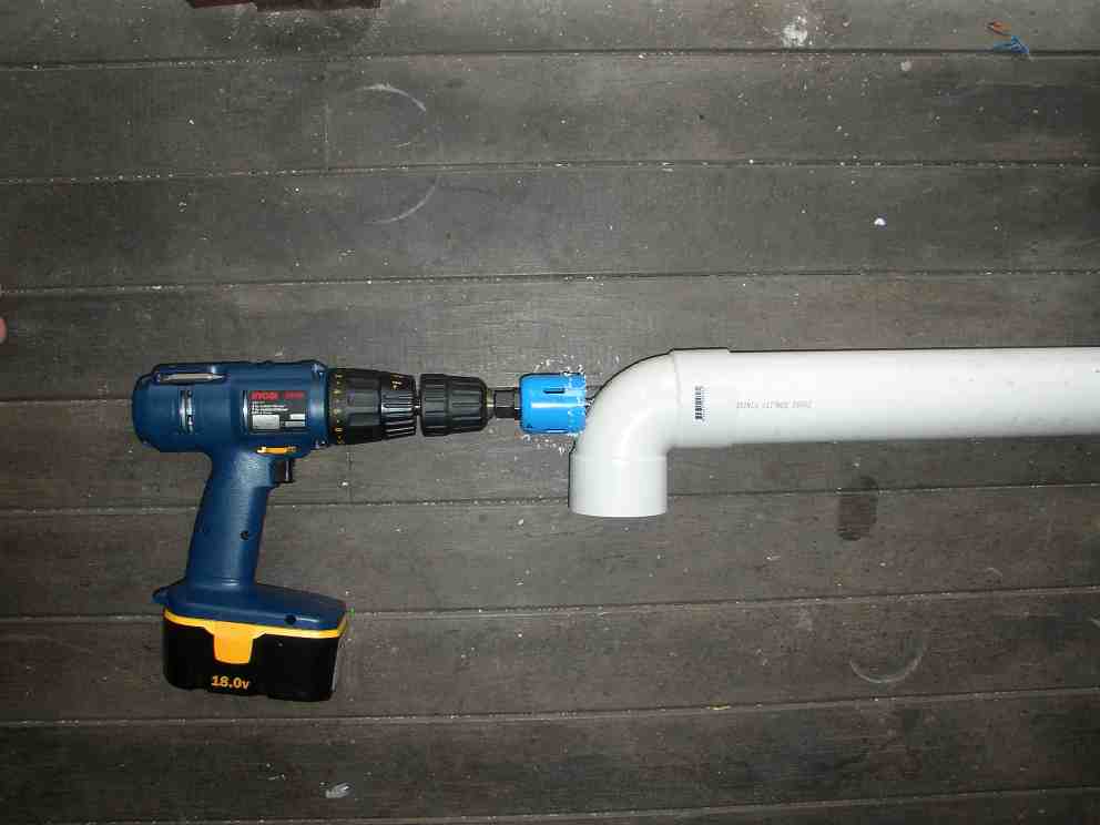
Take the 65 mm PVC elbow and find the centre of the outside of the elbow by measuring along the mould seam from both ends. Mark a position 17 mm away from the centre, along the seam. This is the centre for starting the 43 mm (or 44 mm) hole saw.
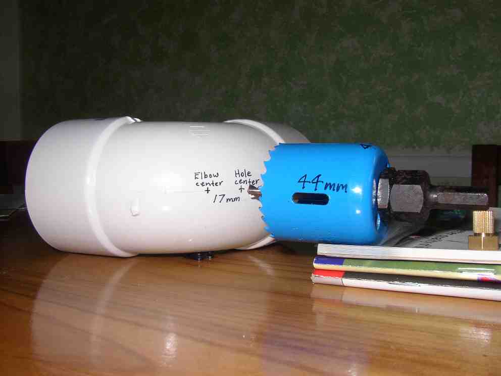
If you have a drill-press or lathe and some way to clamp the pipe-elbow in the right position and orientation, well and good, otherwise: Push the elbow onto a metre or more of 65 mm PVC pipe, e.g. a lift-tube, in the socket farthest from the 17 mm mark. This is to make it easier to hold and align the elbow with the holesaw. I use floorboard joints on my verandah to sight the pipe and drill against. Have a friend hold the pipe, with the other socket of the elbow pointing to that side where the rotation of the holesaw will tend to hold it against the floor. Start the holesaw perpendicular to the surface, at the 17 mm mark, but gradually bring it around so that by the time it passes thru the elbow wall it is aligned with the central axis of the pipe. Slowly and carefully cut the hole, always maintaining the drill in alignment with the central axis of the pipe. Deburr the hole.
Place the inverter-housing through the hole in the elbow so the end with the lamp-supporting disk is inside the elbow. Check that the housing is centered in the elbow socket. Rest them on a flat smooth surface so the bottom of the inverter housing is level with the bottom of the elbow. Rotate the housing until the long axis of the oval hole is at right angles to the central axis of the other elbow socket. Mark the inverter housing where it meets the elbow so you know where to put the cement. Also mark the point where the housing aligns with the mould seam on the elbow. Take the housing out. For aesthetics you can clean off most of the marking with mineral turpentine, leaving just a faint marking. When the turps has dried off, coat it with PVC cement where it will join the elbow. Also coat the inside of the hole in the elbow. Quickly assemble the two and stand them on a flat surface again. Let the cement dry for 5 to 30 minutes then add more cement around the top of the joint to build up a fillet. If you used a 44 mm hole saw you will probably have to do this 3 or 4 times, first to fill up the gap and then to build up the fillet. In this case you should let it dry as long as possible between coats and it may take several days before it is strong enough to handle without special care. Make sure your PVC cement is described as "gap filling". An alternative is to weld it with a soldering iron and PVC scraps cut into filler rods. It is important for this joint to be mechanically strong as the inverter housing will be used to anchor the pump/lift-tube/UV-head to the side of the pond. Note that unlike the photo below, you will have the disk and collar cemented to the inside of the inverter housing at this stage, as shown in the photo after.
Now we silicone the quartz sleeve to the inverter housing using glass and aquarium silicone. Note that this is different from the neutral-cure roof and gutter silicone we use on metal and electrical components. Wait until the elbow to inverter-housing joint is strong enough to handle (at least overnight), but still handle it only by the inverter housing. Remember that the quartz sleeve is fragile and expensive. Clean the inside of the housing and the outside of the quartz tube with mineral turpentine where they will overlap, then allow them to dry. Place the rubber o-ring against the disk inside the inverter housing and press and twist the quartz tube into the o-ring until it sits against the disk. The main purpose of this o-ring is to centre the quartz tube and hold it in place until the silicone cures. If the quartz sleeve ever needs replacing (e.g. after breakage), you will need to cut the silicone with a hobby knife and remove all the old silicone from the housing, before repeating the process described below. Note that unlike the photo below you will have the inverter housing cemented to the 65 mm elbow at this stage.
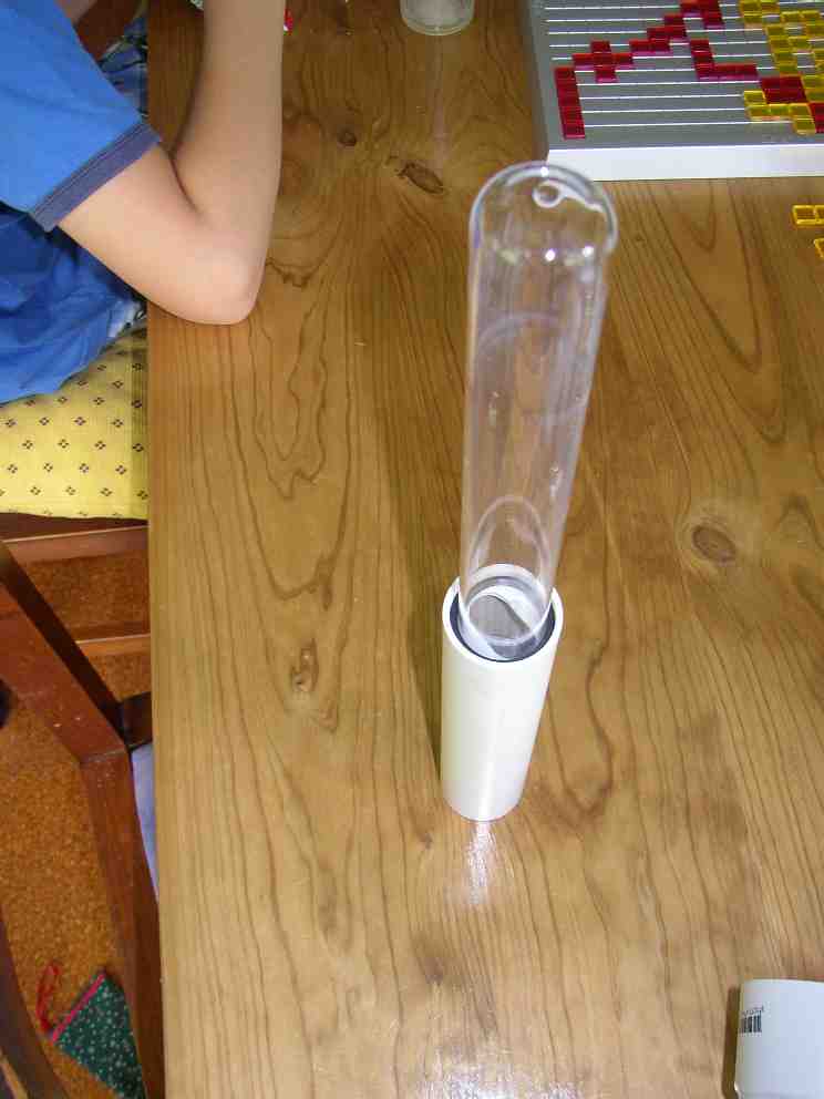
Cut a 250 mm length of 65 mm PVC pipe (or use the outlet tube from an existing pump/lift-tube) which we will temporarily fit into the elbow socket so it surrounds the quartz tube. Only push it in about 20 mm so it will be possible to remove it by hand later. Use it to check that the quartz tube is centred, or at least parallel to the pipe. Nudge the quartz tube gently until this is the case, then carefully remove the pipe. This pipe will be used for protecting the quartz tube during storage and transport and it will eventually be used in the other socket of the elbow as the outlet tube for the system.
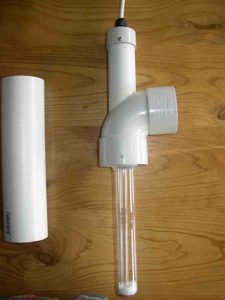
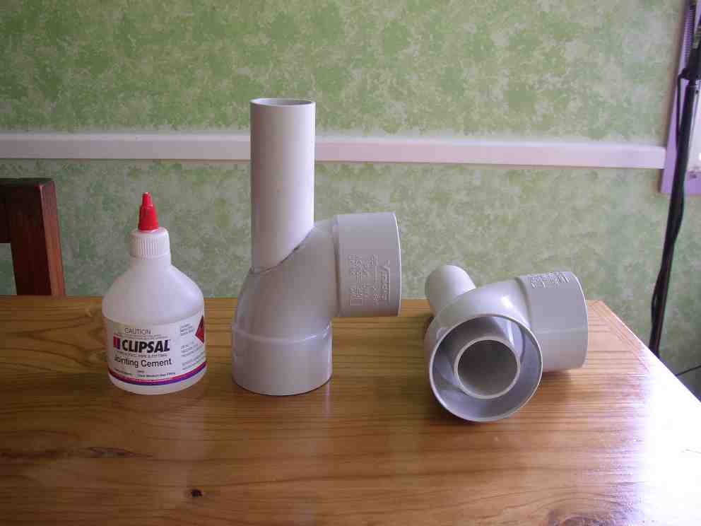
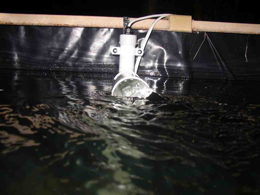
Do not cut off the end of the nozzle on the silicone cartridge, but leave it with a 3 mm opening. Have a friend hold the inverter housing against the bench while you squeeze the silicone as far as possible into the gap above the o-ring and between the PVC housing and the quartz tube. Put the protective piece of pipe back in place and check that the quartz tube is parallel, nudging it gently as required or packing it with paper or rag to hold it in the correct position. Stand the unit vertically in a secure place with the quartz sleeve uppermost, e.g. in a bucket, or taped against a wall by its PVC parts. Let the silicone cure for some hours, preferably overnight. Then remove the protective pipe and use more silicone to build up a 45 degree fillet around the quartz beyond the PVC housing so as to smooth the water flow past this joint when it is in operation. Use a spatula with an 8 mm wide tip (e.g. cut from PVC scrap) to smooth the silicone. You can remove excess silicone from the PVC by wiping immediately with a clean cloth. Don’t try to remove excess from the quartz, it will just smear (unless you use mineral turpentine). You can remove it with a knife after it cures. Place the protective pipe around it again. The silicone will take at least 3 days to cure to sufficient strength to safely withstand the pressure produced when the lamp is powered up and heats the air in the chamber. See the silicone fillet in the photo at the start of this article.
Now we make the lid for the inverter housing. Take a 40 mm PVC end-cap and drill or cut a hole in the middle, of the right size to take the waterproof cable gland (usually either 13 mm (1/2") or 16 mm (5/8")). Coat the gland head, thread and nut with neutral cure silicone so as to seal it to the PVC end-cap both inside and out. Screw it together tightly with the end cap and wipe off excess silicone.
The end cap will only be pushed 10 mm onto the pipe that forms the inverter housing, so that it will be possible to remove it to change the lamp, and so that excess pressure can escape. The end cap will be held on by two diametrically opposed stainless-steel self-tapping screws. Wrap a piece of paper around the end cap and mark the circumference on the paper, then fold this length in half to get a crease and use it to mark the two diametrically opposed screw holes 5 mm in from the edge of the end cap. Mark the inverter housing at a point 10 mm from its end and wrap paper around to mark it all the way around. Push the end cap on until it meets the 10 mm mark, rotated so that the screws (and hence the line between them) will be parallel to the pool edge when the unit is in service. Drill the screw holes through both cap and pipe with a 2 mm (5/64") bit. Then remove the cap and drill the holes in the cap out to 3.2 mm (1/8").
Note that, because of its pressure-relieving ability, this enclosure is not protected against immersion (except briefly), although it is protected against splashes or jets of water. That’s why the electricals inside it must be properly sealed with Plasti-dip to survive deep immersion for long periods, just in case it somehow ends up on the bottom of the pool.
Now we assemble the electrical parts of the UV head. First we’re going to waterproof the inverter. Take the inverter and cut the blue and white wires 30 mm from the outside of the aluminium case. Remove the lid of the aluminium case and remove the circuit board from its case, leaving behind the clear plastic insulator and the black plastic grommets, but retaining the piece of circuit board that holds the two MOSFETs apart.
Cut off the one blue and one white wire that enter the board nearest the two round blue capacitors. Cut these wires as close to the board as possible and ensure that any remaining stubs are not touching each other or anything else. These wires are for heating filaments in four-pin lamps. 11 watt UVC lamps are only available with two pins. The inverter is quite capable of starting the lamp cold.
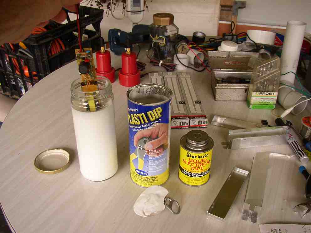
Follow the directions on the can of Plasti-dip, open it outdoors in a well ventilated area. Don’t breathe the fumes and don’t touch it, it contains some very nasty solvents. Holding the inverter circuit board by the red and black wires, lower it verrry slowly into the plasti-dip until it is completely submerged, then remove it just as slowly.
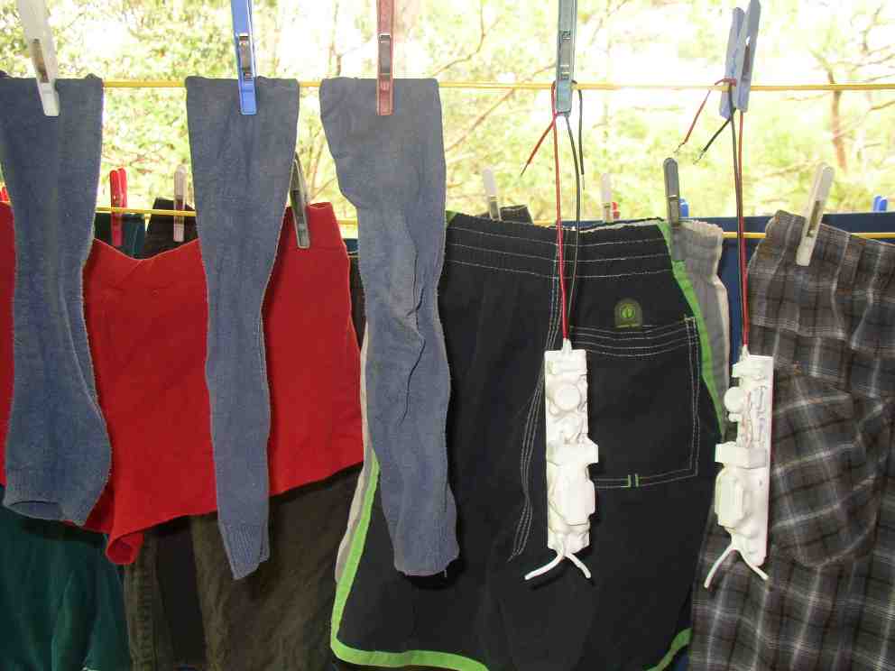
Jiggle it a bit to make any remaining blobs drop off and hang it up to dry in a well ventilated place overnight.
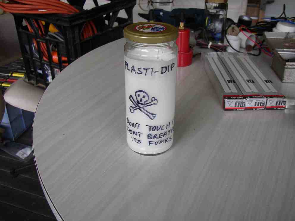
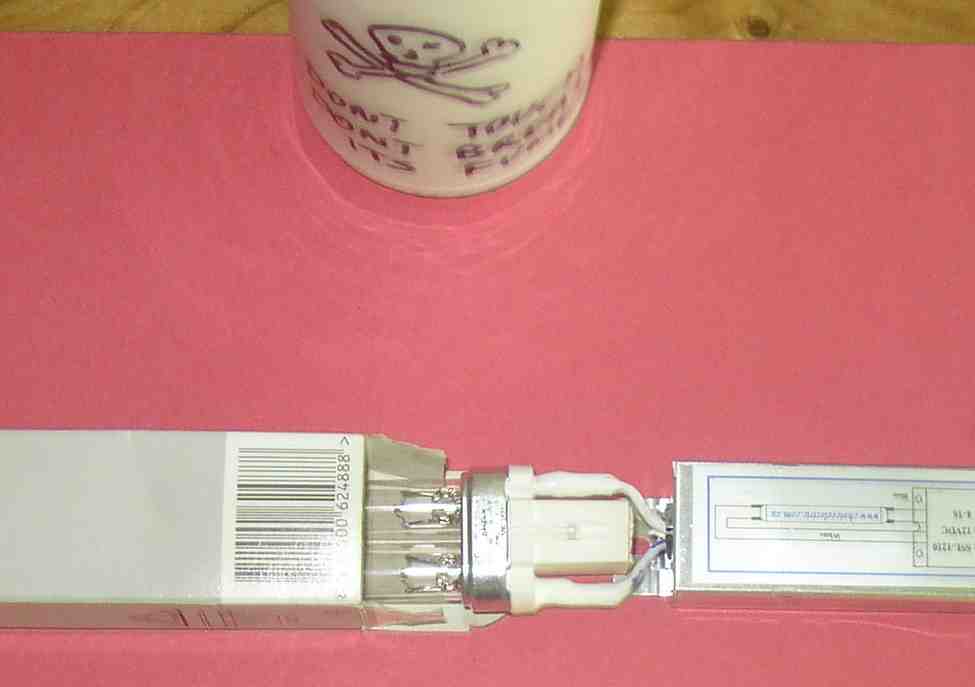
Put the lid back on the Plasti-dip and put it in a safe place out of reach of children. The plastic lid split on mine so I had to pour it into a glass jar with a properly sealing lid. If you do that, be sure to label it with appropriate warnings. A skull and cross-bones looks good too.
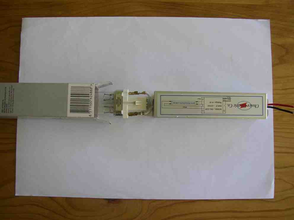
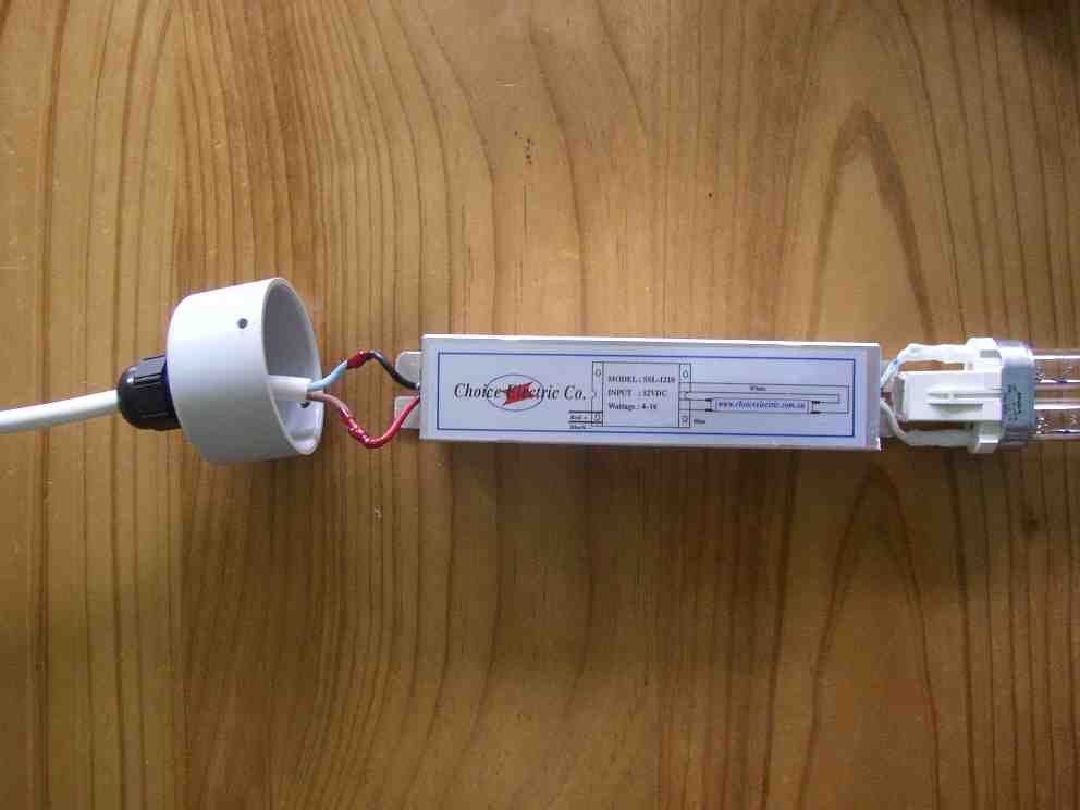
Now we modify the Philips TUV PL-S 11 watt lamp so it will work with the inverter. Many thanks to John Cooper of Choice Electric Co, the makers of the inverter, for telling me about this. The lamp is intended only for use with low frequency (50 or 60 Hz) alternating current with an electromagnetic ("iron") ballast. It has a built-in starter and interference-suppression capacitor in its base. These components would prevent it from working properly with a high frequency inverter (or "electronic ballast"). Philips make four pin versions of their ordinary fluorescent lamps, for use with electronic ballasts, but not so for the UV lamps.
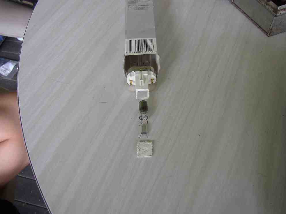
Remember that the lamp is fragile and expensive. Open the box at the end with the white plastic base and slide the lamp out just far enough that you can hold it at the edge of a bench by its metal collar and gently hacksaw off the end of the white plastic base, about 1 mm from the tip. This will expose a silvery rectangular capacitor and two wire connections, each consisting of three wires. Cut all three wires at both connections such that the capacitor and the cylindrical glass starter fall out and can be discarded. You will see two fine wires still inside the base. Clip these off as far inside the base as possible with small sharp electronics-type side-cutters, but be careful not to pull or twist them in any way because they enter the fragile quartz envelope of the lamp. Make sure they are as far apart as possible.
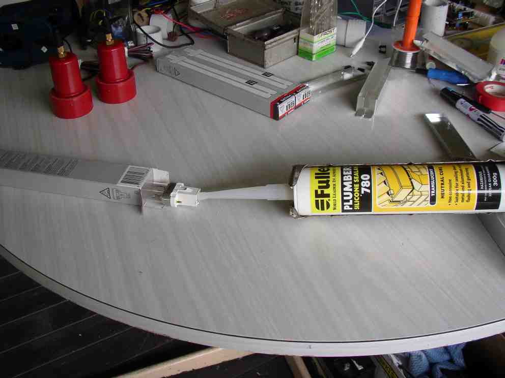
Completely fill the space inside the base with neutral-cure silicone, being sure to cover the ends of the wires. That’s the end of the lamp modification. Put it back in its box for now. Remember to do this modification to all future replacement lamps.
When the inverter circuit board is dry, fill any holes left in the Plasti-dip coating (e.g. those caused by burst bubbles), by dribbling more Plasti-dip into them. There’s no need to waste a brush on this job. Any clean disposable stick such as a match-stick, toothpick, skewer or ice-cream stick will serve to transfer blobs of plasti-dip. Squeeze the inverter back into its aluminium case (with its plastic lining and grommets) and clip the lid on. It will be a tight squeeze, but this aluminium case reduces radio-frequency interference from the inverter. Cut the black and red wires about 30 mm from the case, and strip about 4 mm of insulation from the ends of all four wires.
Take two uninsulated female bullet connectors of the type used in disk drive power connectors. Crimp them onto the blue and white wires, but do not crimp the tabs around the insulation yet. Solder the ends of the wires to the inside of the connectors and wait for the wires to cool before crimping the remaining tabs onto the insulation. All in-pond joints are soldered because this makes them much less prone to corrosion in the damp environment. We could simply solder the wires to the lamp pins, but this would make it difficult to change lamps. The lamps only last one year in continuous operation.
Keeping the lamp mostly inside its packaging, connect the inverter to the lamp via the female bullet connectors and coat the connections completely with Plasti-dip using a disposable stick. Ensure that all metal is covered, that the hole in the bullet connector is filled and that a seal is made with the plastic lamp-base and the wire insulation. Turn the inverter and lamp over and do it from the other side too.
Now take the circular twin core 1mm2 cable and strip 20 mm of outer sheath, then tie a 100 mm cable tie tightly around the cable 25 mm from the end of the sheath (45 mm from the end of the cores). Strip 4 mm of insulation from each core. Solder the blue wire of this cable to the black wire of the inverter and the brown wire to the red wire. Coat these connections with Plasti-dip. Leave it for the Plasti-dip to dry, preferably overnight.
Pass the free end of the circular twin cable through the gland on the end cap and slide the cap towards the inverter until stopped by the cable-tie. Tighten the waterproof gland by hand, but use a spanner to hold the part that is fixed to the outside of the end cap, so as not to disturb its silicone seal.
Clean the lamp quartz with alcohol and a clean cloth or paper towel. Crumple an A4 sized piece of cling-wrap into a ball and push it into the inverter housing and then into the quartz sleeve. This is to stop the lamp banging against the quartz sleeve during transport. It will probably turn to powder under the influence of the UV radiation once the irradiator is in operation. Slide the lamp into the inverter housing and into the quartz sleeve. Look into the quartz sleeve and ensure that the metal lamp collar is properly seated in the oval hole in the PVC disk.
Spread the joints in the red and black inverter wires apart and push the lid onto the inverter housing, aligning the screw holes. Screw in the self-tapping screws until their heads just make contact with the PVC. Do not over-tighten them. Put the 250 mm long piece of 65 mm PVC pipe in place to protect the quartz sleeve.
Installing the pump/lift-tube/UV-head in the pond
At the pond, ensure there is no gravel or other loose material in the hole in the trunk of the completed undergravel filter. Insert the pump/lift-tube fully into the hole in the trunk. Mark the maximum intended water level on the lift-tube. Remove the pump/lift-tube from the pond and cut the lift-tube 95 mm shorter than that mark. If in doubt, leave it a little longer, you can always cut more off later. Deburr it. Mark a line all the way around, 20 mm from the cut end.
On the UV head, we will mark two screw holes that will attach it to the lift tube. We do not glue it on, since we need to be able to remove it to clean the quartz tube, but it must not be possible to remove it without using a tool since the UV-C radiation is very damaging to skin and eyes. Mark these two screw holes diametrically opposed, 10 mm in from the edge of the elbow socket nearest the quartz sleeve, inline with the screws holding the cap on the inverter housing.
Remove the PVC pipe that is protecting the quartz sleeve and push it into the other part of the elbow to become the outlet tube. Push the UV head onto the lift-tube so that the quartz sleeve goes inside the lift-tube. Push it on only until the edge of the elbow meets the 20 mm mark on the lift-tube. Ensure the outlet tube is on the opposite side of the lift-tube from the short piece of electrical conduit at the other end of the lift-tube. You might want to briefly put it back in place in the pond, plugged into the undergravel filter trunk, to check that the outlet tube is at right angles to the pool edge.
Drill the two screw holes with a 2 mm bit, through the elbow and lift tube, but be extremely careful not to penetrate as far as the inverter housing. A short piece of 50 mm pipe should be temporarily placed over the quartz sleeve as a shield. Then remove the UV head from the lift-tube and drill the holes in only the elbow out to 3.2 mm. Reassemble the UV head onto the lift-tube, aligning the screw holes. Screw in the self-tapping screws until their heads just make contact with the PVC. Do not over-tighten them.
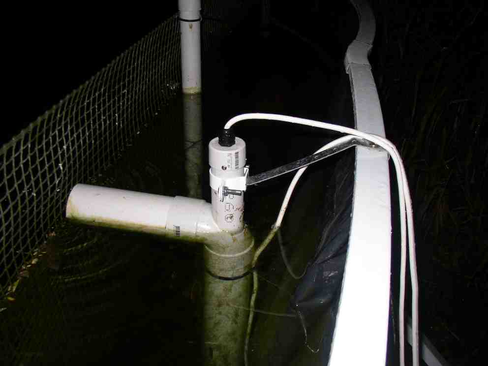
Put the pump/lift-tube/UV-head into the undergravel filter trunk and use a 40 mm pipe hanging bracket (with easily-bent strap) to anchor the inverter housing to the pond coping and thereby stabilise and hold down the lift-tube.
Next we need to build the power-supply and control box.and connect the pump and UV irradiator to it.
The end.